mne.viz.plot_topomap
- mne.viz.plot_topomap(data, pos, vmin=None, vmax=None, cmap=None, sensors=True, res=64, axes=None, names=None, show_names=False, mask=None, mask_params=None, outlines='head', contours=6, image_interp='bilinear', show=True, onselect=None, extrapolate='auto', sphere=None, border='mean', ch_type='eeg')[source]
Plot a topographic map as image.
- Parameters
- data
array, shape (n_chan,) The data values to plot.
- pos
array, shape (n_chan, 2) | instance ofInfo Location information for the data points(/channels). If an array, for each data point, the x and y coordinates. If an Info object, it must contain only one data type and exactly
len(data)data channels, and the x/y coordinates will be inferred from this Info object.- vmin
float|callable()|None The value specifying the lower bound of the color range. If None, and vmax is None, -vmax is used. Else np.min(data). If callable, the output equals vmin(data). Defaults to None.
- vmax
float|callable()|None The value specifying the upper bound of the color range. If None, the maximum absolute value is used. If callable, the output equals vmax(data). Defaults to None.
- cmapmatplotlib colormap |
None Colormap to use. If None, ‘Reds’ is used for all positive data, otherwise defaults to ‘RdBu_r’.
- sensorsbool |
str Add markers for sensor locations to the plot. Accepts matplotlib plot format string (e.g., ‘r+’ for red plusses). If True (default), circles will be used.
- res
int The resolution of the topomap image (n pixels along each side).
- axesinstance of
Axes|None The axes to plot to. If None, the current axes will be used.
- names
list|None List of channel names. If None, channel names are not plotted.
- show_namesbool |
callable() If True, show channel names on top of the map. If a callable is passed, channel names will be formatted using the callable; e.g., to delete the prefix ‘MEG ‘ from all channel names, pass the function
lambda x: x.replace('MEG ', ''). Ifmaskis not None, only significant sensors will be shown. IfTrue, a list of names must be provided (seenameskeyword).- mask
ndarrayof bool, shape (n_channels, n_times) |None The channels to be marked as significant at a given time point. Indices set to
Truewill be considered. Defaults to None.- mask_params
dict|None Additional plotting parameters for plotting significant sensors. Default (None) equals:
dict(marker='o', markerfacecolor='w', markeredgecolor='k',
     linewidth=0, markersize=4)
- outlines‘head’ | ‘skirt’ |
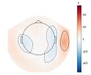
dict|None The outlines to be drawn. If ‘head’, the default head scheme will be drawn. If ‘skirt’ the head scheme will be drawn, but sensors are allowed to be plotted outside of the head circle. If dict, each key refers to a tuple of x and y positions, the values in ‘mask_pos’ will serve as image mask. Alternatively, a matplotlib patch object can be passed for advanced masking options, either directly or as a function that returns patches (required for multi-axis plots). If None, nothing will be drawn. Defaults to ‘head’.
- contours
int|arrayoffloat The number of contour lines to draw. If 0, no contours will be drawn. If an array, the values represent the levels for the contours. The values are in µV for EEG, fT for magnetometers and fT/m for gradiometers. Defaults to 6.
- image_interp
str The image interpolation to be used. All matplotlib options are accepted.
- showbool
Show figure if True.
- onselect
callable()|None Handle for a function that is called when the user selects a set of channels by rectangle selection (matplotlib
RectangleSelector). If None interactive selection is disabled. Defaults to None.- extrapolate
str Options:
'box'Extrapolate to four points placed to form a square encompassing all data points, where each side of the square is three times the range of the data in the respective dimension.
'local'(default)Extrapolate only to nearby points (approximately to points closer than median inter-electrode distance). This will also set the mask to be polygonal based on the convex hull of the sensors.
'head'Extrapolate out to the edges of the clipping circle. This will be on the head circle when the sensors are contained within the head circle, but it can extend beyond the head when sensors are plotted outside the head circle.
Changed in version 0.21:
The default was changed to
'local''local'was changed to use a convex hull mask'head'was changed to extrapolate out to the clipping circle.
New in version 0.18.
- sphere
float| array_like | instance ofConductorModel The sphere parameters to use for the cartoon head. Can be array-like of shape (4,) to give the X/Y/Z origin and radius in meters, or a single float to give the radius (origin assumed 0, 0, 0). Can also be a spherical ConductorModel, which will use the origin and radius. Can also be None (default) which is an alias for 0.095. Currently the head radius does not affect plotting.
New in version 0.20.
- border
float| ‘mean’ Value to extrapolate to on the topomap borders. If
'mean'(default), then each extrapolated point has the average value of its neighbours.New in version 0.20.
- ch_type
str The channel type being plotted. Determines the
'auto'extrapolation mode.New in version 0.21.
- data
- Returns
- im
matplotlib.image.AxesImage The interpolated data.
- cn
matplotlib.contour.ContourSet The fieldlines.
- im